
|
Concrete Masonry Column Design: |
|
This design guide will provide a basic overview of the allowable stress design process for concrete masonry columns as per the requirements of the 2012 IBC and 2011 MSJC Code, Chapter 2.
|
|
In the case of concrete masonry column design, where the structural element may carry significant axial loads, additional moment due to lateral loads or eccentric axial loads
typically reduces the element's axial capacity. Therefore, in the case of masonry column design, the interaction between axial load and moment must be considered.
|
|
|
|
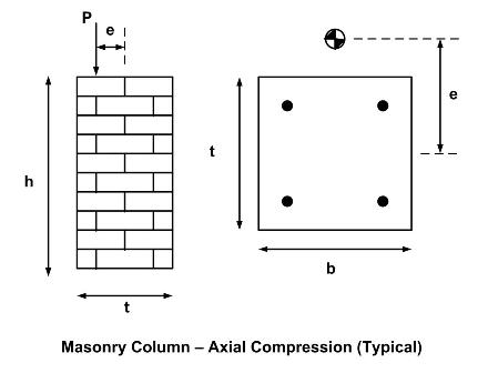
A column, by definition, is an isolated vertical member whose horizontal dimesion measured at right angles to its thickness does not exceed three times its thickness and whose height
is greater than four times its thickness. Columns function primarily as compression members when supporting beams, girders, trusses or similar elements. |
|
|
Column Requirements |
|
Since a column failure may cause the collapse of other structural members, column design must follow a series of special requirements in addition to
the requirements for reinforced concrete masonry wall design.
|
|
|
|
|
Slenderness |
|
|
Column capacity may be reduced due to either buckling or because of additional bending moment caused by deflection. In the MSJC, slenderness
effects are included in the calculation of allowable compressive stress for reinforced masonry. For column design, the MSJC limits the effective
height to thickness ratio to 25, and requires a minimum nominal side dimension of 8 in (203 mm).
|
|
|
The effective column height is typically taken as the clear height between supports. If there is reliable restraint against both translation
and rotation at the supports, the effective height may be reduced in accordance with conventional design principles. |
|
|
The structural capacity of masonry columns is also affected by eccentricity. Eccentricity may occur due to eccentric axial loads,
lateral loads, or the columns is out of plumb. The MSJC requires that the design consider a minimum eccentricity of 0.1 times each side dimension,
with each axis considered independently. This minimum eccentricity accounts for construction tolerances. If the actual eccentricity exceeds this minimum,
then logically the actual eccentricity should be used. |
|
|
|
|
Reinforcement |
|
|
The MSJC requires a minimum amount of vertical column reinforcement as well as lateral ties to confine the vertical steel. Lateral ties are also required to enclose and
support the vertical reinforcement. The size and spacing requirements in the code ensure the ties prevent buckling of reinforcement acting in compression as well as provide shear resistance
to the columns subjected to lateral loads. Vertical lateral ties spacing is reduced to half above the top of the footing or slab ina ny story, as well as bleow the lowest
horizontal reinforcement in a beam, girder, slab, or drop panel above. For the case where beams or brackets frame into a column from four directions, the lateral ties must be placed within 3 in (76 mm) below the lowest
reinforcement in the shallowest beam or bracket. |
|
|
Lateral ties are allowed to be placed in either mortar or grout, although placement in grout is more effective at preventing buckling and results in more ductile behavior. Thus, they are required to be embedded
in grout in Seismic Performance Categories D and E. There are also additional requirements that apply when more than four vertical bars are used. Besides the requirement for corner bars to be laterally supported by
the corner of a lateral tie, alternate bars must also be supported. Additionally, bars not supported by a lateral tie corner must be spaced 6 in (152 mm) or closer on each side along the lateral tie from the laterally supported
bar. When the longitudenal bars are placed in a circle, circular ties are permitted, provided they have a minimum lap length of 48 tie diameters.
|
|
|
|
Additional Requirements in Seismic Performance Categories (SPC) C, D and E
|
|
Columns for buildings in categories SPC C, D and E require are subject to additionan design requirements to help prevent structural failure during an earthquake.
The MSJC requires connectors to transfer forces in SPC C, D and E to ensure proper anchorage between columns and horizontal structural elements. When anchor bolts
are used for this purpose, they must be enclosed by the vertical reinforcement and lateral ties. Additionally, at least 2 - #4 (M 13) lateral ties must be provided within the top 5 in (127 mm) of the column. |
|
Having adequate lateral restraint is also important for column reinforcement receiving seismic forces. Thus, in SPC D and E 3/8 in (9.5 mm) minimum diameter lateral ties are required to be embedded in grout and spaced verticallly nor more than 8 in ( 203 mm) on center.
|
|
|
|
Column Design
|
|
Allowable stress design of concrete masonry columns must comply with the
reinforced masonry design section of the MSJC, Chapter 2.
Column design considers the contribution of vertical reinforcement to the allowable compressive force and assumes proper confinement
of the vertical steel thru the use of lateral ties. |
|
Masonry columns may be connected to horizontal elements of the structure, sometimes relying on these connections for lateral support.
The masonry/mortar bond, mechanical anorage, friction, bearing, or a combination of these may be used to transfer forces at the connection.
Resistance to all loads, moments and shears applied at intersections with horizontal members, must be included in the column design using a force
of at least 1,000 lb (4.4 kN). |
|
The magnitude of the axial load relative to the bending moment dictates the design approach used. The design section will either be in pure compression, with the allowable axial load governed by Pa; be subject to a combined
axial load and flexure with the allowable moment and allowable axial force governed by the allowable flexural compressive stress in masonry, Fb; or be subject to combined axial load and flexure, but governed by the allowable tensile
stress in the reinforcement, Fs. |
|
|
Column in Compression
|
|
If the eccentricity is located within the kern (center 1/3) of the column, the entire section is in compression.
Then capacity is determined by the equations for Pa. Also the MSJC limits the maximum height of column based on acceptable
slenderness ratios.
Check reinforced masonry column for axial compression.
Check maximum height for masonry column in axial compression.
|
|
|
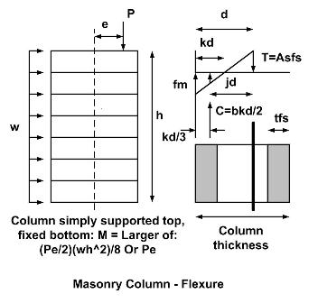
Column Flexure and Shear |
|
When the column recieves a lateral load it must be designed for shear and flexure.
Check the flexural and shear stress in a reinforced masonry column.
|
|
|
Combined Axial Compression and Flexure |

|
When the column axial load is located outside the kern, or the column recieves a lateral load in addition to the axial load, the column is subjected to flexure, resulting in both net compression and tension.
Check reinforced masonry column for axial compression and flexure.
|
|
|
Biaxial Bending |

|
When the column is subject to biaxial bending or flexural loading from two different directions the axial capacity must be reduced to account for the biaxial bending loads.
Check axial load capacity for masonry column subjected to biaxial bending.
|
|
|