
|
Concrete Floor Design:
|
|
This design guide is intended to provide guidance for the safe design and economical
construction of suspended concrete floor slabs. This design guide and the corresponding
calculations are based on the requirements of ACI 318 and strength design method
where the capacity of the beam is designed to support factored loads.
Slabs are structural elements whose lengths and widths are large in comparison to
their thicknesses. Unlike beams, shear is generally carried by the concrete
without the aid of shear reinforcement. Longitudinal reinforcement is used
to resist bending moments. The slab thickness is typically governed by deflection
criteria or fire rating requirements.
|
Design of Two-way Slabs:
|
|
|
|
Slabs are defined as two-way slabs when the ratio of long-to-short sides is less
than 2. There are four types of two-way slabs. (a) A flat plate which is a
two-way slab supported on a column grid without the use of beams. (b) A flat slab
which is the same as a flat plate except the areas around the columns have increased
thicknesses, called drop panels, to increase the shear capacity at the columns.
(c) A waffle-slab which is similar to the flat plate except there are voids left
out in the areas away from the columns resembling a waffle. (d) Conventional slab
construction similar to the one-way slab with beams supporting the floor and resting
on top of columns.
|
|
Direct Design Method, DDM: The DDM can be used
when the following conditions are met: (a) There are a minimum of 3 spans. (b) Panels
are rectangular with a ratio of long-to-short side (center-to-center of supports)
of no more than 2. (c) Successive span lengths do not differ by more than one third
of the longest span. (d) Columns are not offset by more than 10% of the span in
the direction of the offset. (e) The loading consists of uniformly distributed gravity
loads. (f) The service live load does not exceed 2 times the dead load. (g) If beams
are present, the relative stiffness in 2 perpendicular directions is not less than
0.2 nor grater than 5.0.
|
|
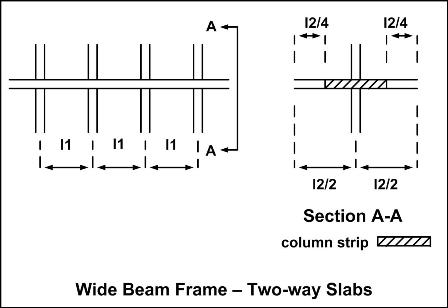
1. Divide the floor system in each direction into wide beams as shown below:
|
|
|
2. Calculate the total statical moment in each span as Mo = wul2ln^2/8. This
moment is the maximum moment in a simple beam of span ln that carries the total
load (wul2). In the equation the span l2 refers to the width of the wide beam
being considered. ln is measured face-to face of columns or other supports.
However, ln >= 0.65 l1. For the computation of minimum thickness in two-way
slabs, ln is taken as the distance face-to-face of supports in slabs without beams
and face-to-face of beams or other supports in other cases.
|
3. Divide the total moment, Mo, in each span into positive and negative moments.
For interior spans, the negative factored moment is calculated as 0.65Mo, and the
positive factored moment is 0.35 Mo. The total moment in end (exterior) spans
is distributed according to the coefficients in the table below:
|
Distribution of Moments in Exterior Spans
(fraction of Mo)
|
|
|
|
Slabs without
beams between
Interior supports
|
|
|
|
Exterior edge
unrestrained
|
Slab with beams
between
all supports
|
Without
edge
beam
|
With
Edge
beam
|
Exterior edge
fully restrained
|
|
Interior negative
factored moment
|
.075
|
0.70
|
0.70
|
0.70
|
0.65
|
|
Positive factored
moment
|
0.63
|
0.57
|
0.52
|
0.50
|
0.35
|
|
Exterior negative
Factored moment
|
0
|
0.16
|
0.26
|
0.30
|
0.65
|
|
|
4. Divide the width of the wide beam into column-strip and middle-strip regions.
A column strip is a design strip with a width of each side of the column centerline
equal to 0.25l2 or 0.25l1, which ever is less. A middle strip is a design
strip bounded by 2 column strips.
|
|
5. Design the column strip for the fractions of the moment at each section according
to the following table:
|
Distribution of Moments in Column Strips
(fraction of Mo)
(a is relative stiffness, Bt is the relative torsional
stiffness)
|
(a) Interior
negative moment
|
|
l2/l1
|
|
0.5
|
1.0
|
2.0
|
|
a1 l2/l1=0
(no beams)
|
|
0.75
|
0.75
|
0.75
|
|
a1 l2/l1 >=1
|
|
0.90
|
0.75
|
0.40
|
|
(b) Exterior
negative moment
|
|
l2/l1
|
|
0.5
|
1.0
|
2.0
|
|
a1 l2/l1 = 0
|
Bt = 0
|
1.00
|
1.00
|
1.00
|
|
a1 l2/l1 = 0
|
Bt >=2.5
|
0.75
|
0.75
|
0.75
|
|
a1 l2/l1 >= 1
|
Bt = 0
|
1.00
|
1.00
|
1.00
|
|
a1 l2/l1 >= 1
|
Bt >= 2.5
|
0.90
|
0.75
|
0.45
|
|
(c) Positive
factored moment
|
|
l2/l1
|
|
0.5
|
1.0
|
2.0
|
|
a1 l2/l1 = 0
(no beams)
|
|
0.60
|
0.60
|
0.60
|
|
a1 l2/l1 >= 1
|
|
0.90
|
0.75
|
0.45
|
|
The distribution of moments in two-way slabs depends on the relative stiffness of
the beams, a, with respect to the slab without beams. The relative stiffness,
a, is the ratio of the flexural stiffness of a slab of width equal to that of the
wide beam (i.e., the width of a slab bounded laterally by the centerlines of adjacent
panels).
a = EcbIb/(EcsIs)
where:
Ecb = moment of elasticity of the concrete beam
Ib = moment of inertia of the concrete beam
Ecs = moment of elasticity of the concrete slab
Is = moment of inertia of the concrete slab
|
The distribution of the negative moment across the width of a slab at the exterior
edge depends not only on the relative beam stiffness and the ratio l2/l1, but also
on the stiffness in torsion of edge beams.
Relative torsional stiffness, Bt = EcbC/(2EcsIs)
C = summ of (1 - 0.63(x/y))(x^3y/3) The summation is taken over all the separate
rectangles that make up the edge beam. The division into separate rectangles
that leads to the largest value of C should be used.
|
|
6. Design the middle strip for the fractions of the moment at each section not assigned
to the column strip.
|
|
Deflections in Two-Way Slabs:
|
|
To avoid calculating deflections in two-way slabs the slabs should be sized for
the following minimum thickness values:
|
Minimum Thickness for Slabs Without Interior Beams
(longest clear span divided by value of given)
|
|
without drop panels
|
with drop panels
|
|
|
Exterior panels
(in)
|
Interior
panels
(in)
|
Exterior panels
(in)
|
Interior
panels
(in)
|
|
yield
strength
(psi)
|
without
edge
beams
|
with
edge
beams
|
|
without
edge
beams
|
with
edge
beams
|
|
|
40,000
|
33
|
36
|
36
|
36
|
40
|
40
|
|
60,000
|
30
|
33
|
33
|
33
|
36
|
36
|
|
75,000
|
28
|
31
|
31
|
31
|
34
|
34
|
|
|
For slabs without beams or whose beams are only placed between exterior columns
(i.e., slabs without beams between interior supports), minimum thickness is specified
as the largest clear span (face-to-face of supports) divided by the values listed
in the table above. for the values in the table to be useful, drop panels
must project below the slab at least 1/4 of the slab thickness beyond the drop and
must extend in each direction at least 1/6 the length of the corresponding span.
The thickness of the slab without drop panels may not be less than 5 in. Slabs
with drop panels may not be less than 4 in thick.
|
For the purpose of calculating minimum thickness in slabs with beams between interior
supports, there are three possibilities. For am <= 0.2, the minimum thickness
is computed neglecting the beams. For 0.2 < am <= 2.0, the minimum thickness
is given in the equation below where B is the ratio of clear spans in the long-to-short
directions.
h = ln(0.8 + fy/200,000)/(36 + 5B(am - 0.2)) >= 5 in
for am > 2.0, the minimum thickness is
h = ln(0.8 + fy/200,000)/(36 + 9B) >= 3.5 in
When the stiffness ratio a of the edge beam is less than 0.8, the minimum thickness
in the edge panel shall be at least 10% larger than the value obtained in the equations
above.
|