
|
Concrete Masonry Design: |
|
The design of concrete masonry walls can be achieved by several different methods allowed by the 2012 International Building Code, IBC,
and the 2011 Building Code Requirements for Masonry Structures, MSJC Code:
allowables stress design, strength design, direct design or empirical design. This
design guide will provide a basic overview of the allowable stress design process as per the requirements of the 2012 IBC and 2011 MSJC Code.
|
Allowable stress design is based on the following design principles or rules:
- Masonry elements satisfy applicable conditions of equilibrium and compatibility of strains within the range of allowable stresses.
- Stresses remain in the elastic range.
- Strains in masonry and reinforcement are directly proportional to the distance from the neutral axis. Plane sections before bending remain plane after bending.
- Within the allowable stress range, stress is linearly proportional to strain.
- The resistance of any reinforcement is neglected in unreinforced masonry design.
- All tensile stresses are resisted by the reinforcement in reinforced masonry design. The masonry in tension does not contribute to axial or flexural strength.
- The masonry units, mortar, grout, and reinforcement, if present, all act compositely to resist applied loads.
|
|
|
|
Basically, in allowable stress design of masonry the calculated design stresses on a masonry member are compared to the code-prescribed maximum allowable stresses. Thus, the design is acceptable when the calculated applied stresses are less than or equal
to the allowable stresses as prescribed in the code. |
|
|
Design of Unreinforced Masonry |
|
For unreinforced masonry, the masonry assembly is designed to carry all the applied stresses. Any additional capacity that might be provided by reinforcement required in the assembly for control of shrinkage and cracking or as might be required by code requirements is neglected.
Because the masonry is designed to resist both tension and compression stresses from the applied stresses, the masonry must remain uncracked.
|
|
|
|
|
Unreinforced Out-of-Plane Flexure |
|
|
|
The compressive strength of masonry is much larger than its tensile strength. Therefore, the capacity of unreinforced masonry subjected to net
flexural stresses is almost always controlled by the flexural tension values.
Check the Flexural/Shear Stress in an unreinforced masonry wall.
|
|
|
|
|
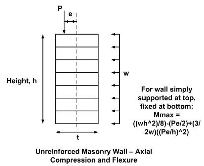
Unreinforced Axial Compression and Flexure |
|
|
Even though unreinforced masonry can resist flexural tension stresses due to applied loads, it is not permitted to be subjected to net axial tension, such as from wind uplift on a roof connection or from a lateral load.
Although compressive stresses from dead loads can offset tensile stresses, reinforcement must be incorporated into the design to resist the resultant tensile forces when the wall is subject to a net axial tensile load.
When masonry is subjected to compressive axial loads only, the calculated compressive stress due to the applied load, fa, must not exceed the allowable compressive stress, Fa.
|
|
Stability against an eccentrically applied axial load must also be checked and is included in the equations where the axial compressive load, P,
is limited to one-fourth the buckling load, Pe. The actual eccentricity of the applied load, e, is used to determin Pe.
When the masonry is subjected to both axial load and flexure, a unity equation is used to proportion the available allowable stresses for the applied loads.
Check the Axial Compression/Flexural/Shear Stresses in an unreinforced masonry wall.
|
|
|
|
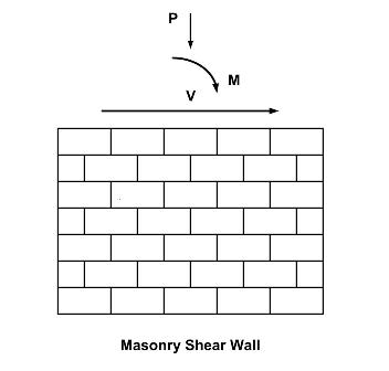
Unreinforced Shear
|
|
For unreinforced masonry the net cross-sectional properties of the masonry in the direction of the applied shear force is used to calculate the shear stress.
For a rectangular cross section, the theoretical distribution of shear stress, fv, along the length of the shear wall for in-plane loads, or perpendicular to any wall for out-of-plane loads, is parabollic in shape.
Design an unreinforced masonry shear wall.
|
|
|
|
Reinforced Masonry
|
|
Per the MSJC Code, the strength of the reinforced masonry assemblage neglects the tensile resistance provided by the masonry units, mortar and grout.
Thus, for the design, the portion of the masonry subjected to the net tensile stresses is assumed to have cracked, transferring all tensile forces to the reinforcement.
|
|
|
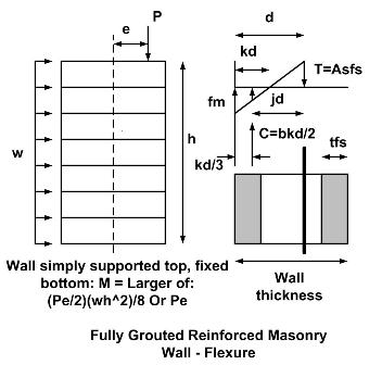
Reinforced Out-of-Plane Flexure
|
|
When axial loads are not present, or when they are conservatively neglected, there are several things to consider when determining the capacity of reinforced masonry.
For a fully grouted element, a cracked transformed section approach is used, wherein the reinforcement area is transformed to an equivalent area of concrete masonry.
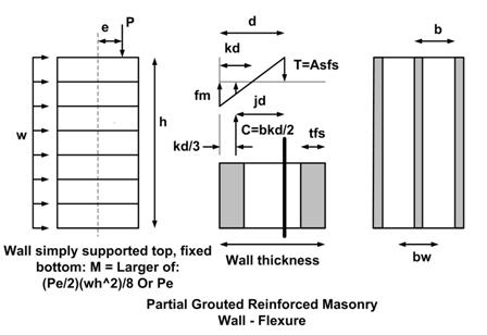
Partially grouted assemblies are analyzed in the same way, but with the additional consideration of the ungrouted cores. For partially grouted masonry there are two
types of behavior to consider.
1. When the neutral axis (the location of zero stress) lies within the compression face shell. In this case, the masonry is designed using the same procedure as for
fully grouted masonry, a rectangular beam analysis.
Check the flexural stresses in a fully grouted reinforced masonry wall.
2. When the neutral axis lies within the hollow core area for this case the the protion of the ungrouted cells must be deducted from the area of masonry capable of carrying the compression
stresses. This analysis is known as a tee beam analysis.
Check the flexural stresses in a partially grouted reinforced masonry wall.
|
|
|
Reinforced Axial Compression |
|
The allowable axial compressive force for reinforced masonry is based on the compressive strength of the masonry and its slenderness ratio.
Check reinforced masonry wall for axial compression.
|
|
|
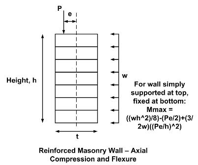
Reinforced Axial Compression and Flexure |
Often a bearing wall may be eccentrically loaded. Superimposing the stresses resulting from axial compression and flexural compression produces the combined stress. Members are
proportioned so that this maximum combined stress does not exceed the allowable stress limitation imposed as appropriate. One should note that in cases where the combined compressive
stresses are relatively large, it may be more efficient to specify a larger masonry compressive strength which in turn can result in a thinner wall cross-section, reduced material usage and increased construction productivity.
Check reinforced masonry wall for axial compression and flexure. |
|
|
Reinforced Shear |
|
|
|
For reinforced masonry, the shear resistance provided by the masonry is added to the shear resistance provided by the shear reinforcement.
This is a change from previous versions of the code, but provides a better prediction of the shear strength.
|
|
There are two checks that are made for reinforced masonry shear design. First, as for all ASD design, the calculated shear stress must be less than or equal to the allowable shear stress, (fv <= Fv). Next, when the calculated shear stress is greater
than the allowable shear stress resisted by the masonry, (fv > Fvm), shear reinforcement must be provided. |
Additionally, when fv > Fvm, shear reinforcement mus be provided as per the following code requirements:
- shear reinforcement must be parallel to the direction of shear
- spacing of the shear reinforcement must not exceed the lesser of d/2 or 48 in (1,219 mm)
- additional reinforcement must also be provided perpendicular to the shear reinforcement. Additional reinforcement must have an area of
at least Av/3, must be uniformly distributed and may not be spaced farther apart than 8 ft (2,438 mm)
|
Check reinforced masonry wall for shear stress.
Design shear reinforcement for reinforced masonry wall. |