
|
Spread Footing Design Process: |
|
The design of spread footings is somewhat simplified when you follow the step by
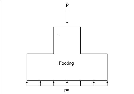
step process below. The purpose of a foundation is to distribute the loads of the
building or structure to the soil in such a way that the soil will bear the load.
In layman’s terms the purpose of the foundation and in this case the spread footing
is to distribute the load to the soil without exceeding the bearing capacity of
the soil. Hence the very first step in the process of designing the spread footing
is to calculate the area required to support the vertical load on the soil. The
following is a simplified step by step process for the design of a spread footing:
|
|
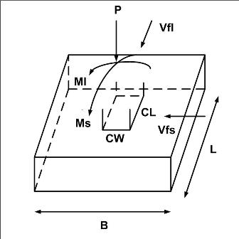
1. Determine the
area required for a trial design section and choose the initial dimensions,
(i.e., width, B and length, L), based on the allowable soil pressure or bearing
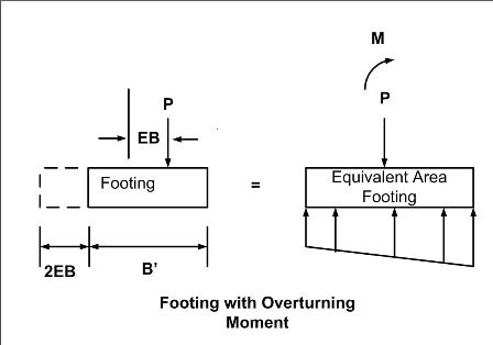
capacity. If it is necessary for the load on the footing to be off center, insure
that the load is centered on one axis, (preferably the long axis), and on the middle
third of the overall footing area along the other axis. Size the overall footing
so that the reduced area due to the eccentricity, E, is equivalent to the area required
for the trial design section. The reduced area places the equivalent force at the
centroid of a reduced area.
|
|
|

|
For a non-centered load the eccentricity is: EB = MB/P; EL = ML/P
The equivalent area dimensions are: L’ = L - 2EL; B’ = B - 2EB
With the equivalent area: A’ = L’B’
|
|
|
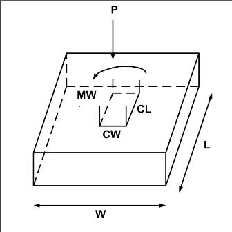
2. Check the maximum and minimum
soil pressures resulting from an applied moment load. Either a moment load
from a lateral load on the column or from the eccentricity from the off center load
on the footing. If there is no moment load ML then:
|
|
ppmax, pmin =(P/BL)( 1+or- 6EB/B)
|
|
|
3. Adjust the area if the minimum soil pressure is negative, or if the maximum exceeds
the allowable soil pressure. A negative minimum soil pressure means that the soil
pressure resultant is not distributed over the entire area of the footing. Even
if the maximum pressure is below the soil bearing capacity, this situation could
cause other problems, such as uneven long term settlement issues, as well as the
area is not economical.
|
|
4. If there is an applied shear load against the footing, check the footing’s resistance
to sliding as in the design of retaining walls, (see retaining wall design).
|
|
|
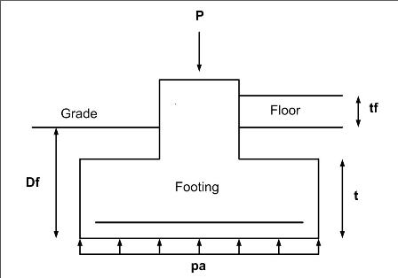
5. Validate the trial design section
area accounting for soil surcharges from adjacent floor loads etc. Always
use normal weight concrete. In my experience there has never been any reason for
light weight concrete in a foundation, and the additional weight is used to add
ballast to the structure against uplift loads. If there is serious uplift
loading, check uplift resistance of the
footing.
|
|
6. Next begin with trial section thickness, depth to steel (d) and check the 1-way shear and
2-way (punching) shear. If the applied load is a vertical load only, 2-way
shear always rules. As stated above normal weight concrete is always used.
|
|
|
7. Design the flexural steel.
Rather than design the steel for the flexural stress in each section and each direction,
which is how many methods and codes allow and many text books will design it. It
is my experience that the construction cost of purchasing, stocking and tying several
different sizes of steel reinforcement negates the savings realized by the smaller
steel cross sections and differing spacing, therefore I recommend determining the
area of steel required for the critical section and then specifying the same size
and spacing for the spread footing throughout and in both directions.
|
|
8. Check the development length
of the flexural reinforcement.
|
|
9. Check the column dowel size
and development length.
|