
|
Reinforced Concrete Cantilever Retaining Wall Design: |
|
This design guide is intended to provide guidance for the safe design and economical
construction of reinforced concrete cantilever retaining walls. Although the reference
covers such, this guide is intended for retaining walls which will not be subject
to hydraulic loadings such as flowing water, submergence, wave action, and spray,
exposure to chemically contaminated atmosphere, and/or severe climatic conditions.
Retaining walls must be designed so that foundation pressures do not exceed allowable
bearing pressures, wall settlements are tolerable, safety factors against sliding
and overturning are adequate, and the wall possesses adequate structural strength.
The design of retaining walls can be simplified by following a careful step by step
process as follows.
|
|
1. Determine the horizontal loading on the wall and the overturning moment. There
are several methods for determining the horizontal resultants on the wall. If the
only loading is a simple soil load, reasonable resultants can be found from the
Rankine or Coulombs Formula for
walls up to 20 feet high. Also the horizontal resultants can be calculated for surface
surcharge loading for a
uniform load surcharge, a
strip load surcharge, a
ramp load surcharge, a
triangle load surcharge, a
point load surcharge or
line load surcharge on the soil behind the wall. However the Army COE
reference seems to prefer the approximate wedge method to determine the horizontal
resultant on a wall for soil with or without a strip load. For most cases it is
recommended to use the
wedge method except in the case of simple loads, and then use the other methods
for comparison to the results of the wedge analysis. In order to determine the horizontal
loading by the wedge method
one must first determine the
slip plane angle. Once the
slip plane angle has been determined then the horizontal resultant and overturning moment by the wedge method
may be determined.
|
|
|
|
In the absence of geotechnical information the cohesion of clay soils can be estimated
as follows: Cohesion, c = 0.0 for sandy, non-plastic, non-cohesive
soils, 100 psf for semi-cohesive soils, or 200 to 400 psf for cohesive clay soils.
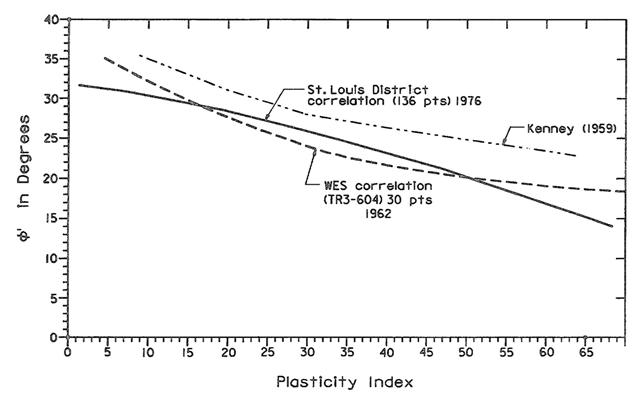
Also the angle of internal friction, AIF of the soil, (shown as the greek symbol
"theta" in the charts), needed to determine soil loading against the retaining
wall may be determined from the reference manual charts shown below.
|
|
For determining AIF for clay soils use the Platicity Index, PI below to approximate
a design AIF:
|
|
|
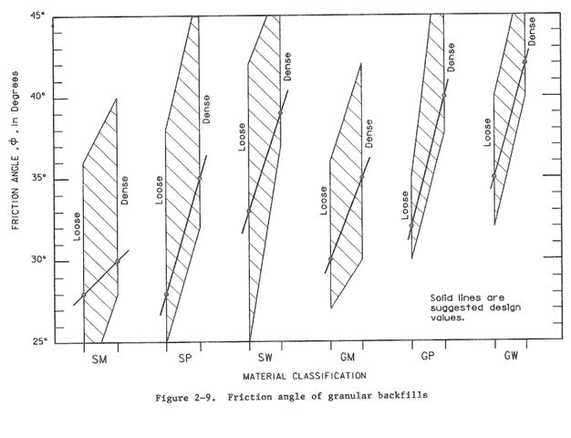
For determining AIF for granular soils, use the soil classification below to determine
AIF:
|
|
|
2. Develop the trial design
from the required resisting moment and safety factors.
|
|
3. Check the resistance to
sliding for a wall with a key, or for a wall without a key.
|
|
4. Determine the sum of the vertical resultants from the soil loading on the wall
applied to the heel. This is referred to as the structural wedge by the reference.
The vertical resultant of the soil is equal to the volume of soil directly over
the heel multiplied by the soil density. If a surface strip load is present directly
above the heel it is added. It is considered a simple enough calculation to be performed
by hand.
|
|
5. Determine the bearing capacity. In the process of checking bearing capacity one
will determine the eccentricity
and maximum and minimum soil bearing pressure and bearing pressure resultants. Then using the information
from these calculations, check the
bearing capacity.
|
|
6. Calculate the required flexural
steel area and temperature shrinkage steel for the stem section.
|
|
7. Calculate the required flexural
steel area for the heel section.
|
|
8. Calculate the required flexural
steel area for the toe section.
|
|
9. Check the development length
of the steel in the stem section.
|